Tuesday, 30 December 2014
High Speed Photography Project Part 2
Hardware Continued.
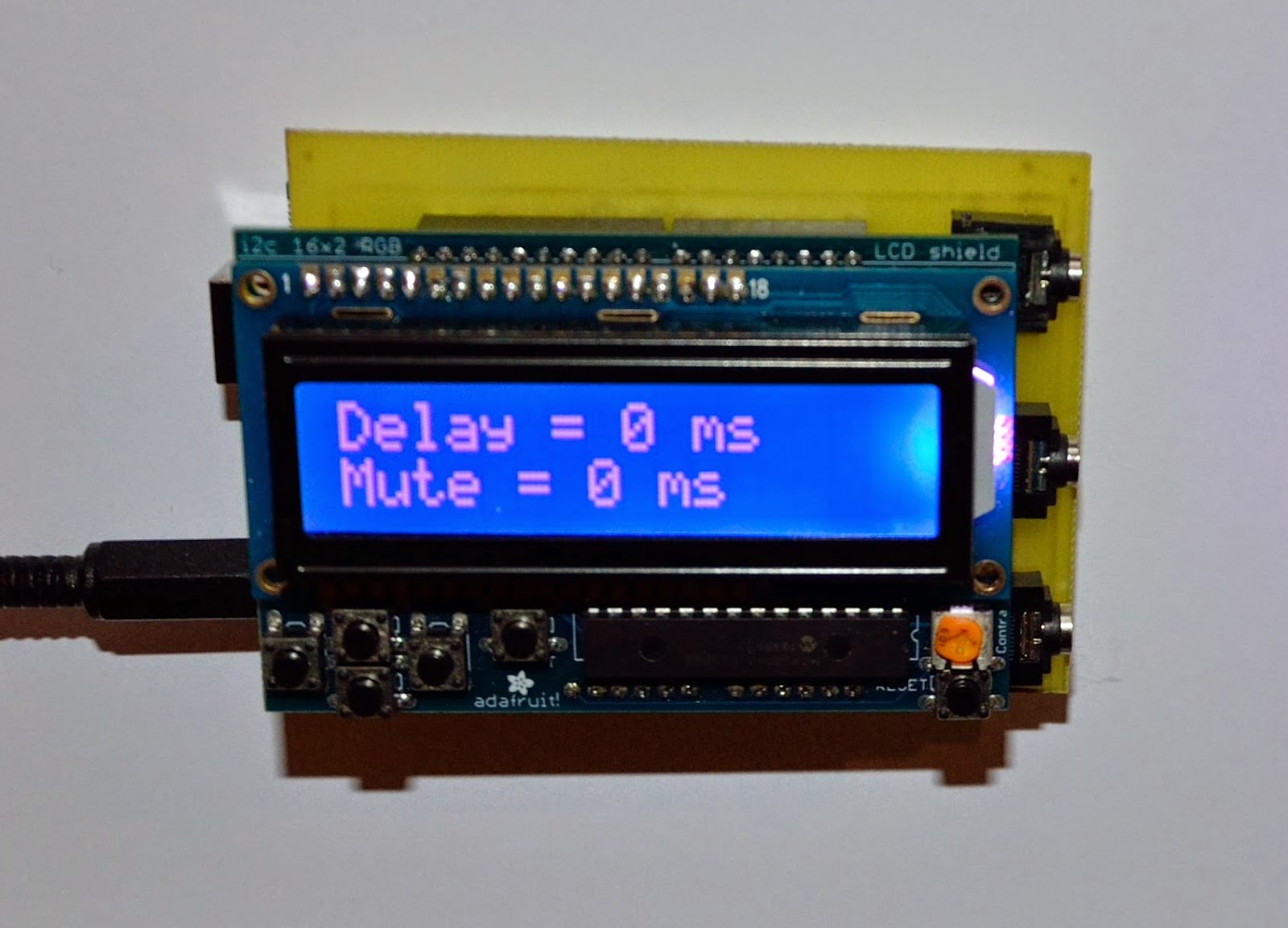
The 3 jack sockets provide input from the sound and light sensors whilst the third is the output for the flash unit.
Programming input is achieved via the push buttons. This provides input of delay time in milli- seconds. This is the duration between 'sensor stimulus' and the flash firing. Two buttons provide +/- increments.
The mute time is the duration the system is locked and will not respond the further stimulus. This is vital when operating in 'bulb mode' since it will inhibit the flash once the initial flash has occurred. It is user defined by two buttons again providing +/- increments.
I have designed a PCB to make construction easier and will upload the Eagle files later once I have refined it from the prototype.
Subscribe to:
Post Comments (Atom)

No comments:
Post a Comment