Software
The software script is listed below. At the moment it is very basic and requires ongoing work. The next stage is to add a menu option that will enable the user to select the 'sound' or 'light' option. At the moment if both elements of the code co-exist in the sketch it can cause some issues.
The sketch below has both elements contained within, however the you need to comment out either section. I would suggest saving two scripts, one for sound and one for light, it is easy to upload whichever you are using.
The display driver and button code is open source and provided by: www.Adafruit.com
#include <Wire.h>
#include <Adafruit_MCP23017.h>
#include <Adafruit_RGBLCDShield.h>
Adafruit_RGBLCDShield lcd = Adafruit_RGBLCDShield();
// These #defines make it easy to set the backlight color
#define RED 0x1
#define YELLOW 0x3
#define GREEN 0x2
#define TEAL 0x6
#define BLUE 0x4
#define VIOLET 0x5
#define WHITE 0x7
// constants won't change. Used here to
// set pin numbers:
int laserPin = 11; //Laser input
const int ledPin = 12; // Digital signal set pin
int val = 0;
const int thresholdvalue=200;//Mic Sensitivity
// Variables will change:
unsigned int Delay = 0; //Delay Time Variable
unsigned int Mute = 0; //Mute Time Variable
//---------------------------------------------------------------
void setup() {
// Setup Digital & Analogue pin mode:
pinMode(ledPin, OUTPUT);
pinMode(laserPin, INPUT);
Serial.begin(9600);
// Setup welcome screen:
// setup the LCD's number of columns and rows:
lcd.begin(16, 2);
lcd.print("FLASH CONTROLLER");
lcd.setCursor(0,1);
lcd.print(" ver: 1.8");
lcd.setBacklight(WHITE);
delay(5000);
lcd.begin(16, 2);
lcd.print(" SYSTEM ACTIVE");
lcd.setCursor(0,1);
lcd.print(" ENTER TIMES");
lcd.setBacklight(RED);
delay(4000);
}
uint8_t i=0;
void loop() {
//-----------------Sound Trigger Delay Code -----------------------
int sensorValue = analogRead(A0);//use A0 for Mic input
if(sensorValue>thresholdvalue)
{
delay(Delay); // Delay from Trigger input to Flash
digitalWrite(ledPin,HIGH);
lcd.clear();
lcd.print (" INACTIVE ");
lcd.setCursor(0,1);
lcd.print(" SYSTEM MUTED ");
delay(Mute); // Time sensor is inhibited:
lcd.clear(); // Display Delay and Mute Time:
lcd.print("Delay = "); lcd.print(Delay); lcd.print(" ms");
lcd.setCursor(0,1);
lcd.print("Mute = "); lcd.print(Mute); lcd.print(" ms");
lcd.setBacklight(VIOLET);
}
else
{
digitalWrite(ledPin,LOW);
// Serial.println(sensorValue); //Sensitivity Setup Aid - Serial Monitor
}
//-----------------Laser Trigger Delay Code -----------------------
//int val = digitalRead(laserPin);
//Serial.println(val);
//if(val>0)
//{
// delay(Delay);
//digitalWrite(ledPin,HIGH);
// lcd.clear();
// lcd.print (" INACTIVE ");
// lcd.setCursor(0,1);
// lcd.print(" SYSTEM MUTED ");
// delay(Mute);
//lcd.clear(); // Display Delay and Mute Time:
// lcd.print("Delay = "); lcd.print(Delay); lcd.print(" ms");
// lcd.setCursor(0,1);
// lcd.print("Mute = "); lcd.print(Mute); lcd.print(" ms");
// lcd.setBacklight(VIOLET);
// }
// else
//{
// digitalWrite(ledPin,LOW);
// }
//---------------------Button Control---------------------------
uint8_t buttons = lcd.readButtons();
if (buttons)
lcd.clear();
lcd.setCursor(0,0);
if (buttons & BUTTON_UP) {
delay(100); // wait for contact settle
Delay = Delay + 10;
lcd.print ("Delay = "); lcd.print(Delay); lcd.print(" ms");
lcd.setBacklight(RED);
}
if (buttons & BUTTON_DOWN) {
delay(100); // wait for contact settle
Delay = Delay - 10;
lcd.print ("Delay = "); lcd.print(Delay); lcd.print(" ms");
lcd.setBacklight(YELLOW);
}
if (buttons & BUTTON_LEFT) {
delay(100); // wait for contact settle
Mute = Mute - 1000;
lcd.print("Mute = "); lcd.print(Mute); lcd.print(" ms");
lcd.setBacklight(GREEN);
}
if (buttons & BUTTON_RIGHT) {
delay(100); // wait for contact settle
Mute = Mute + 1000;
lcd.print("Mute = "); lcd.print(Mute); lcd.print(" ms");
lcd.setBacklight(TEAL);
}
if (buttons & BUTTON_SELECT) {
lcd.clear();
lcd.setCursor(0,0);
lcd.print("Delay = "); lcd.print(Delay); lcd.print(" ms");
lcd.setCursor(0,1);
lcd.print("Mute = "); lcd.print(Mute); lcd.print(" ms");
lcd.setBacklight(VIOLET);
}
}
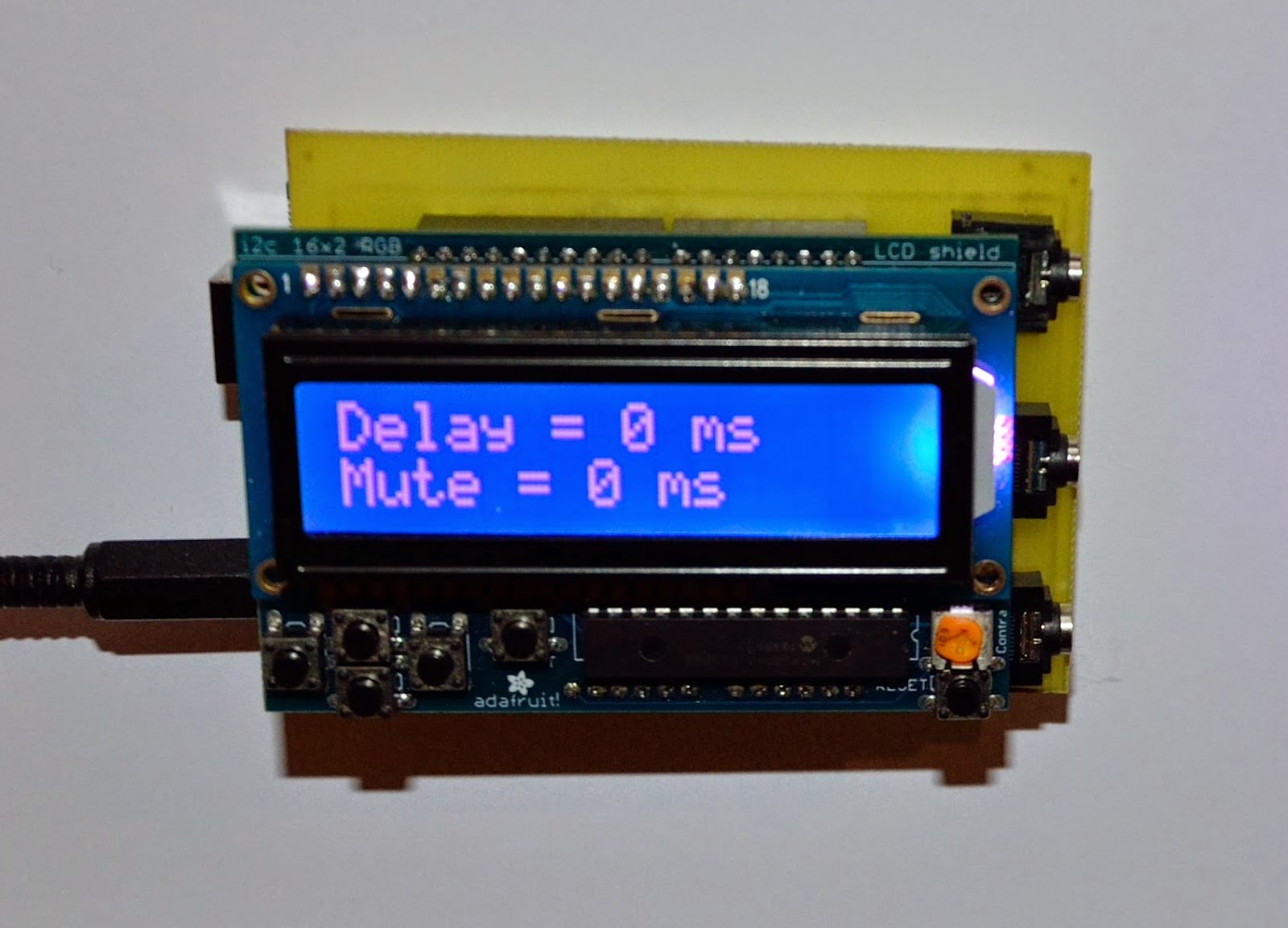
First Test Picture